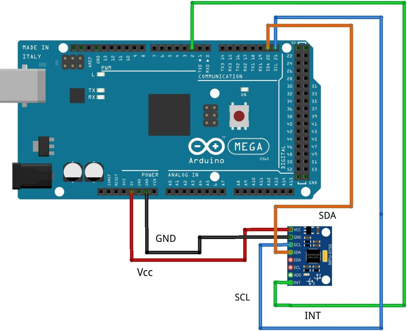
Arduino pins<------------------------->MPU-9250 pins
5V<------------------------->VCC
GND<------------------------->GND
SCL (21)<------------------------->SCL
SDA (20)<------------------------->SDA
Digital PIN2<------------------------->INT
راهاندازی ماژول IMU نه محوره MPU9250 توسط آردوینو
همه مقالات ->
همه مقالات 3879
2 کاربر آکادمی پارتینه
آنالیز حرکتی یکی از مفاهیم اساسی در تحلیل رفتار یک سیستم به شمار میرود. برای برقراری ارتباط به صورت بلادرنگ باید قادر باشید تا با پارامترهای حرکتی مانند شتابخطی، شتاب زاویهای و جهت مغناطیسی ارتباط برقرار کنید.
معرفی ماژول IMU نه محوره MPU9250
ماژول MPU9250دارای نه محور است که سه محور برای ژیروسکوپ، سه محور برای شتاب و سه محور برای میدان مغناطیسی استفاده میشود . این ماژول دارای دقت بسیار بالا و سیستم پیشرفته پردازش حرکت دیجیتال داخلی (DMP) می باشد و از طریق دو پروتکل ارتباطی I2C و SPI میتواند با پردازنده ارتباط برقرار کند. وجود سه محور برای میدان مغناطیسی مشکل وجود انباشتگی (Drift) در مقادیر سرعت زاویهای را کاملا حل کرده است.
مواد اولیه :
| # | عنوان | تعداد | لینک |
|---|---|---|---|
| 0 | سیم جامپر | 1 | لینک خرید |
| 1 | خرید برد آردوینو | 1 | لینک خرید |
| 2 | ماژول IMU نه محوره MPU9250 | 1 | لینک خرید |
مرحله 1 : اتصالات و دیاگرام مداری
مرحله 2 : کدنویسی و تنظیمات نرمافزاری

در گام اول کتابخانههای مورد نیاز را فراخوانی میکنیم. کتابخانه "Wire.h" مربوط به پروتکل I2C بین آردوینو و ماژول MPU9250 است.
#include <Wire.h>
#include <TimerOne.h>
طبق اطلاعات دیتاشیت آدرس سخت افزاری پروتکل I2C برای شتابسنج و ژیروسکوپ 68 هگز و برای مگنومتر 0C هگز است.
#define MPU9250_ADDRESS 0x68
#define MAG_ADDRESS 0x0C
در قسمت voide setup رنج تغییرات سه سنسور (شتابسنج - ژیروسکوپ - مگنومتر ) مشخص کرده، همچنین فیلتر پایینگذر داخلی را برای شتابسنج و ژیروسکوپ فعال میکنیم.
void setup()

{

// Arduino initializations

Wire.begin();

Serial.begin(115200);

// Set accelerometers low pass filter at 5Hz

I2CwriteByte(MPU9250_ADDRESS,29,0x06);

// Set gyroscope low pass filter at 5Hz

I2CwriteByte(MPU9250_ADDRESS,26,0x06);

// Configure gyroscope range

I2CwriteByte(MPU9250_ADDRESS,27,GYRO_FULL_SCALE_1000_DPS);

// Configure accelerometers range

I2CwriteByte(MPU9250_ADDRESS,28,ACC_FULL_SCALE_4_G);

// Set by pass mode for the magnetometers

I2CwriteByte(MPU9250_ADDRESS,0x37,0x02);

// Request continuous magnetometer measurements in 16 bits

I2CwriteByte(MAG_ADDRESS,0x0A,0x16);

pinMode(13, OUTPUT);

Timer1.initialize(10000); // initialize timer1, and set a 1/2 second period

Timer1.attachInterrupt(callback); // attaches callback() as a timer overflow interrupt

// Store initial time

ti=millis();

}

// Counter

long int cpt=0;

void callback()

{

intFlag=true;

digitalWrite(13, digitalRead(13) ^ 1);

}
در حلقه اصلی برنامه مقادیر رجیسترهای مربوط به شتابسنج، ژیروسکوپ و مگنومتر را در یک مقدار 16 بیتی خوانده و در سریال مانیتور آردوینو نمایش میدهیم.
void loop()

{

while (!intFlag);

intFlag=false;

// Display time

Serial.print (millis()-ti,DEC);

Serial.print ("\t");

// _______________

// ::: Counter :::

// Display data counter

// Serial.print (cpt++,DEC);

// Serial.print ("\t");

// ____________________________________

// ::: accelerometer and gyroscope :::

// Read accelerometer and gyroscope

uint8_t Buf[14];

I2Cread(MPU9250_ADDRESS,0x3B,14,Buf);


// Create 16 bits values from 8 bits data

// Accelerometer

int16_t ax=-(Buf[0]<<8 | Buf[1]);

int16_t ay=-(Buf[2]<<8 | Buf[3]);

int16_t az=Buf[4]<<8 | Buf[5];

// Gyroscope

int16_t gx=-(Buf[8]<<8 | Buf[9]);

int16_t gy=-(Buf[10]<<8 | Buf[11]);

int16_t gz=Buf[12]<<8 | Buf[13];

// Display values

// Accelerometer

Serial.print (ax,DEC);

Serial.print ("\t");

Serial.print (ay,DEC);

Serial.print ("\t");

Serial.print (az,DEC);

Serial.print ("\t");

// Gyroscope

Serial.print (gx,DEC);

Serial.print ("\t");

Serial.print (gy,DEC);

Serial.print ("\t");

Serial.print (gz,DEC);

Serial.print ("\t");

// _____________________

// ::: Magnetometer :::

// Read register Status 1 and wait for the DRDY: Data Ready

uint8_t ST1;

do

{

I2Cread(MAG_ADDRESS,0x02,1,&ST1);

}

while (!(ST1&0x01));

// Read magnetometer data

uint8_t Mag[7];

I2Cread(MAG_ADDRESS,0x03,7,Mag);

// Create 16 bits values from 8 bits data

// Magnetometer

int16_t mx=-(Mag[3]<<8 | Mag[2]);

int16_t my=-(Mag[1]<<8 | Mag[0]);

int16_t mz=-(Mag[5]<<8 | Mag[4]);

// Magnetometer

Serial.print (mx+200,DEC);

Serial.print ("\t");

Serial.print (my-70,DEC);

Serial.print ("\t");

Serial.print (mz-700,DEC);

Serial.print ("\t");

// End of line

Serial.println("");

// delay(100);

}
کد کامل برنامه:
#include <Wire.h>
#include <TimerOne.h>

#define MPU9250_ADDRESS 0x68
#define MAG_ADDRESS 0x0C

void setup()
{
// Arduino initializations
Wire.begin();
Serial.begin(115200);

// Set accelerometers low pass filter at 5Hz
I2CwriteByte(MPU9250_ADDRESS,29,0x06);
// Set gyroscope low pass filter at 5Hz
I2CwriteByte(MPU9250_ADDRESS,26,0x06);


// Configure gyroscope range
I2CwriteByte(MPU9250_ADDRESS,27,GYRO_FULL_SCALE_1000_DPS);
// Configure accelerometers range
I2CwriteByte(MPU9250_ADDRESS,28,ACC_FULL_SCALE_4_G);
// Set by pass mode for the magnetometers
I2CwriteByte(MPU9250_ADDRESS,0x37,0x02);

// Request continuous magnetometer measurements in 16 bits
I2CwriteByte(MAG_ADDRESS,0x0A,0x16);

pinMode(13, OUTPUT);
Timer1.initialize(10000); // initialize timer1, and set a 1/2 second period
Timer1.attachInterrupt(callback); // attaches callback() as a timer overflow interrupt


// Store initial time
ti=millis();
}

// Counter
long int cpt=0;

void callback()
{
intFlag=true;
digitalWrite(13, digitalRead(13) ^ 1);
}

// Main loop, read and display data
void loop()
{
while (!intFlag);
intFlag=false;

// Display time
Serial.print (millis()-ti,DEC);
Serial.print ("\t");


// _______________
// ::: Counter :::

// Display data counter
// Serial.print (cpt++,DEC);
// Serial.print ("\t");


// ____________________________________
// ::: accelerometer and gyroscope :::

// Read accelerometer and gyroscope
uint8_t Buf[14];
I2Cread(MPU9250_ADDRESS,0x3B,14,Buf);

// Create 16 bits values from 8 bits data

// Accelerometer
int16_t ax=-(Buf[0]<<8 | Buf[1]);
int16_t ay=-(Buf[2]<<8 | Buf[3]);
int16_t az=Buf[4]<<8 | Buf[5];

// Gyroscope
int16_t gx=-(Buf[8]<<8 | Buf[9]);
int16_t gy=-(Buf[10]<<8 | Buf[11]);
int16_t gz=Buf[12]<<8 | Buf[13];

// Display values

// Accelerometer
Serial.print (ax,DEC);
Serial.print ("\t");
Serial.print (ay,DEC);
Serial.print ("\t");
Serial.print (az,DEC);
Serial.print ("\t");

// Gyroscope
Serial.print (gx,DEC);
Serial.print ("\t");
Serial.print (gy,DEC);
Serial.print ("\t");
Serial.print (gz,DEC);
Serial.print ("\t");


// _____________________
// ::: Magnetometer :::


// Read register Status 1 and wait for the DRDY: Data Ready

uint8_t ST1;
do
{
I2Cread(MAG_ADDRESS,0x02,1,&ST1);
}
while (!(ST1&0x01));

// Read magnetometer data
uint8_t Mag[7];
I2Cread(MAG_ADDRESS,0x03,7,Mag);

// Create 16 bits values from 8 bits data

// Magnetometer
int16_t mx=-(Mag[3]<<8 | Mag[2]);
int16_t my=-(Mag[1]<<8 | Mag[0]);
int16_t mz=-(Mag[5]<<8 | Mag[4]);


// Magnetometer
Serial.print (mx+200,DEC);
Serial.print ("\t");
Serial.print (my-70,DEC);
Serial.print ("\t");
Serial.print (mz-700,DEC);
Serial.print ("\t");


// End of line
Serial.println("");
// delay(100);
}
برای نوشتن نظرات ابتدا وارد حساب کاربری خودشوید.
یا